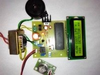
Water is a very important part of everybody’s life. We have water tanks at various places like residential buildings, industries, restaurants, and farms. Everyone is facing the water overflow and wastage problem on day to day basis. And thus comes the need for the water level alarm circuit. This simple DIY project can be the best solution for this problem.

₹ 2,900
Project Code: 1095

Description of the project:
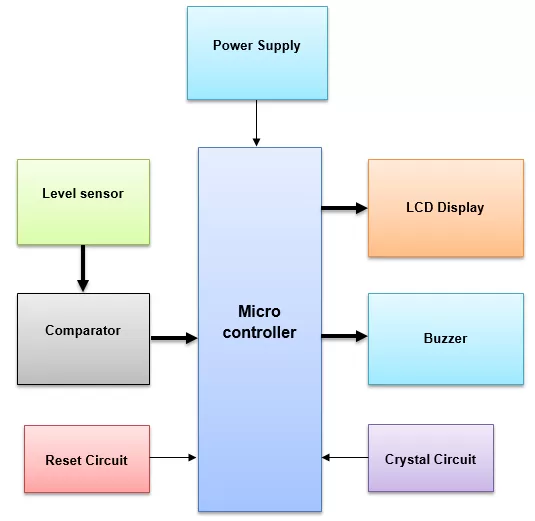
8051 microcontroller is the main part of this project (89s51 to be specific). We have used a float sensor In this project. This float sensor is used to detect the level of the water inside a water tank. Ideally, this sensor should be attached to the top lid of the water tank or the liquid tank. The float attached to the sensor will move up and down as the water level increases or decreases.
89s51 microcontroller can not read analog input. So, the output voltage from the sensor is given to a comparator circuit. The comparator has second input from a variable resistor (potentiometer). The voltage provided by the potentiometer decides the output level of the comparator. Thus, the variable resistor is used to decide the threshold water level for which the buzzer should be turned on.
The benefit of having a potentiometer in the circuit:
The potentiometer and the sensor together provide an extra feature to this project. Other water level alarm circuits do not have a user-defined threshold level. For example: If any project uses a float or probes then the threshold water level is fixed. However, a user can define their own threshold level using the potentiometer in this project.
Output devices in water level alarm circuit:
This project comes with three output devices. These output devices are an LED, an LCD display, and Buzzer.
- On the output side, we have the main component to alert the user and that is a piezoelectric buzzer. This buzzer is turned on whenever the water level is above the threshold level.
- We have also used a 16x 2 Liquid crystal display in this project (widely known as an LCD display). It displays the respective message whenever the water level alarm is turned on.
- This project also has a Red LED for the visual indication of the threshold level. LED and buzzer are activated at the same time.
Use of the toggle switch in the water level alarm circuit:
We have provided a toggle switch in this project. This toggle switch can be used to decide whether the buzzer should be turned on for a high level or a low level.
For example
- If the toggle switch is at an ON position then the buzzer will be activated when the water level is high (or it goes above a threshold level)
- If the toggle switch is at an OFF position then the buzzer will be activated whenever the water level is low (or when it goes below a threshold level)
Applications, Advantages, and Future enhancement for the project
- Water level alarm circuit using an 8051 microcontroller has application in various areas like hotels Restaurants domestic purpose use As well as industries.
- This circuit can also be used for other liquids like fuel, and oil.
- This water overflow alarm system will help in reducing water wastage. Because many times water tank gets overflown when nobody notices it.
- We have provided a 9-volt DC adapter with this project, however, this project can be operated with a 9-volt battery.
- This is easy to use water overflow indicator circuit.
- We can add a relay in this circuit and then this circuit can be used to turn off the water pump whenever the overhead tank is full.
Block diagram of the project Water Level Alarm Circuit:

Software used in Water Level Alarm Circuit project:
- Keil software — Used to write an embedded C language program for a Water level alarm circuit.
- EAGLE software — Used to design PCB layout of Water level alarm project.
- USB ISP Programmer — Used to download hex files into the 8051 microcontroller.
